Friday, January 16, 2009

A Cocking Handle for My RWS (Diana) Model 45, Part 1

"But Nick, I thought you already made a cocking handle/muzzle brake for your Original (Diana) 45?" Well I did. But I bought a RWS branded Diana 45 at the gun show last week.

Slightly different than the Original 45.

The only flaw, a chiseled out chunk of stock.

Unlike the Original 45, it only has the stamped front sight grooves on top, not underneath as well.

I decided to go even chunkier this time, and make the handle out of steel. Drilling 2" deep.

Following with a 1/2" drill, 2" deep.

Drilling another 1-1/2" deep with the 1/4" bit. Because I drilled out to 1/2" chips had someplace to go.

Drilling 11/16"

Then drilling deeper with the 1/2" bit.

Turning a taper.

Filed and blended.

I milled six grooves with a 5/16" ball end mill.

Finding center.

Drilled 3 holes to tap #4-40.

The 11/16" drill I was using previously wasn't long enough so I finished up with a MT2 shank drill.

I drilled 1//4" from the other end.

Turning a taper on the front.

Countersunk.

My new favorite abrasives, 3M bristle wheels.

I used Brownells Dicropan T-4 to blue it. Not done yet!

Wednesday, January 14, 2009

Derrick Fabricates a Wide Trigger, Part 2

Derrick finishes up his trigger...

I fed just a bit of solder at both ends hoping it didn't overfill too badly. Gave it some time to cool.

Checked both sides and it looks like I got a full solder line.

I started removing the oxidation with a round file then realized this would take far too long.

Drill presses aren't just for drilling holes anymore. Here's a cheap small sanding drum. I just grabbed one from the box that was small enough to reach inside the curve.


Sand until it fits your finger and take off all the sharp corners. Made it smooth. Took out all the marks from the ill-fated round metal file from a few pictures above.

Here's how it came out after the sanding drum. These drums are really nice. Run at very low speeds and you can contour the part by hand. Technically, it's completely useable right now, but I'll take it to the buffing wheel and make it look like I paid crazy money for it. I don't think it's correct to call it a trigger shoe now. I think it's just a wide trigger.

I handed it to Kathy and I don't think she believed I made it. It's really bling.

Derrick's verbal amble: Regular readers can see that I often have a miserable time shooting the pics. It takes a lot of discipline to stop and pick up the camera. And I don't have a suitable camera or the steadiness of hand to take good close ups. I've (more than once) shot 100 images and had exactly zero come out the way I wanted. It's not so fun to do the project a second time because of the pics. I went to a heavy hitter for the next picture. My coworker Douglas Charnock is a wizard with a camera. He took this pic with his macro lens. Took him maybe 60 seconds from the time I asked him if he could do it to the final shot. Camera is always at the ready. He took ONE picture, looks up and says, "got it". He ended up taking 2 other shots to appease me, but his first shot was the shot. Thanks Doug! Yeah. This thing is smooooooth.

I was about to reinstall the trigger when I remembered that Pringles potato chip-looking little pressure washer used to take up the trigger's side play in the frame. Better late than never, right? I scrounged up a couple small brass washers and did a quick check on the frame's width where the trigger sits. It was in the ballpark of 0.164". The trigger is 0.125" at the pivot pin hole.

Seems I did want that micro torch after all. It was all of $8. Cheap. Could have done the whole thing with it! I cleaned, fluxed and soldered the brass washers to each side. Used an old pin punch through the holes to line it all up. The hex nuts in the pic were just used against the brass washers for pressure. (The solder won't stick to the stainless steel nuts.) The micro torch was surprisingly easy to give pinpoint heat. I was able to go back and add solder to a couple impossibly small voids. No way to have done that with a full size torch. The whole job would've come apart from the heat.

I had to grind a bit off the washers to get the width right. Reamed the hole to 0.125" . Buffed again on the polishing wheel and installed with a new pivot pin. Noticed that my trigger pin was wearing, so I chopped off a 0.394" length of drill rod that was 1/8" in diameter.

Done. The trigger's face is now approximately 1/2" wide and smooth as can be. Next time, I would angle the face of the trigger toward the trigger finger by about 10 degrees. There's now a target gun inspired (go figure) trigger design floating around in my head for the 22XX series. I'm going to look in the scrap box and see what happens.

Tuesday, January 13, 2009

Derrick Fabricates a Wide Trigger, Part 1

Derrick came up with a fun project last week:

We've both mentioned making a modification to the trigger blade on the Crosman 22XX series CO2 guns. There's not a thing wrong with the $9 trigger shoe from Crosman's custom shop. I've got 3 or 4 of those shoes. I wanted an easy project.

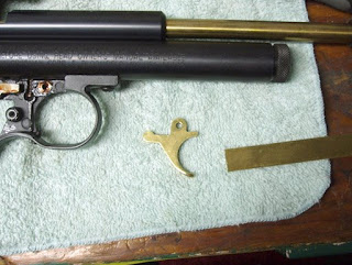
Here's a 2250 trigger blade. I think it's 5/32" thick. Without a trigger shoe to add width, it's painfully thin--to my finger at least--after 20 or so shots. The same trigger is used on the 13XX and 22XX guns as well as some of the older models. Since the trigger is solid brass, why not solder a piece of brass plate to the face of the blade and make an integral shoe?

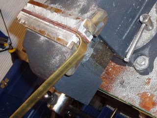
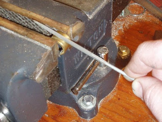
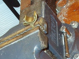
Found a piece of suitable 1/2" wide brass strip laying around. It's 3/32" thick. Cavalier as always about non-critical tolerance fits, I held one end in a vise and bent it around by hand.

Initially, there was a glimmer of idea to wrap the brass strip around an appropriately sized cylinder. Turns out , that's a lot harder to do than it sounds. The brass, isn't that eager to bend to my will. Being a complete hack at heart, I just bent it as close as possible by hand in the vise.

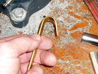
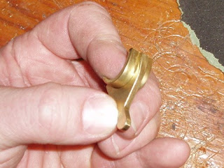
I ended up with this. The radii were promising.
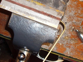
Close enough.

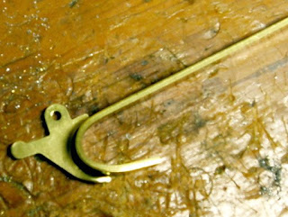
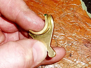
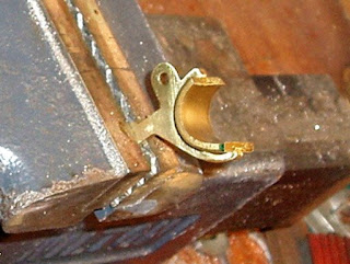
A couple quick magic marker lines and I hacksawed the ends leaving just the curve for the trigger. I decided at this point to do the bulk of the metal removal and final shaping after I'd soldered the parts together. Why? Easier to test fit my trigger finger to the unitized trigger parts.

Another quick eyeball and back to the vise for a bit of filing and rough clean up.

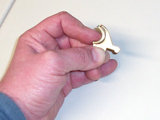
Crosman mashes the bottom of the stock trigger to make it very slightly wider at the base. It also interrupts the arc at the bottom. I filed a bit of metal from what will be the bottom of the trigger shoe.

Another test fit.

Who needs layout fluid when there's a big green Sharpie within reach? At this moment, I realized that I got lucky. Had I used a thicker piece of brass strip than 3/32", the trigger's face would now be too small for my finger. It would have been salvageable, but a substantial amount of time would have to be spent removing the excessively thick brass.

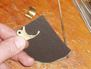
Sanded the surfaces to get clean metal for the solder. I chose to use 220 grit aluminum oxide paper because exhaustive, independent research has proven that it was on the top of my sandpaper box. If you're British, it's perfectly acceptable to use cabinet paper.

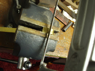
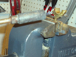
Here's my work holding jig. I know. Deluxe. You should see my budget for fixtures.

Gravity makes for a fine holding device.

Fluxed with some appropriate plumbing-type stuff and out came the propane torch. If I make anymore of these, I'll get a cheap micro torch. There's benefit in heating small areas later to add and remove solder for cosmetic reasons.

Sunday, January 11, 2009

Fixing a Stripped Powerlet Screw Thread on the Crosman 38T

So I had a few minutes of free time and decided to do some plinking in the back yard. Went to charge my .22 38T with gas and somewhat terrifying "whoosh!" all the gas shot out between the cartridge and the sealing unit. After calming down a bit I checked the pistol and found the powerlet screw thread in the frame was stripped. It allowed just enough pressure to pierce the cartridge but then would move from the back pressure. Darn.

You can see the aluminum in the threads of the powerlet screw (#38C-045).

I carefully pried off the cup (#38-131).

You can see how the internal threads are stripped.

Lots of aluminum wrapped around the screw.

So I drilled out the hole to a letter "Q" drill.

And tapped it 3/8"-24 (fine thread)

I turned down a piece of steel to 3/8", drilled and tapped for the 1/4"-28 thread of the powerlet screw.

Then tapped it 3/8"-24

Threads...

I put a very shallow screw driver slot in the end.

And parted it off to length.

Looks good? I then deburred it all over.

I used red loctite to make sure it stayed in place and screwed it flush with the frame.

Inside the frame.

I pressed the cup back on.

Looking at this I wish I'd refinished the end of the screw...that the slot is so abused can only mean someone reefed down on it with some force, which is probably why the threads ended up stripping. Well, I'm the one who only buys used guns...so it's par for the course. You only need a tiny bit of force to seal and pierce the CO2 cartridge, which is why the manual (.pdf) says to use a coin, not a screwdriver to pierce the CO2 cartridge!

The repair seems to have worked well, although I'll check it nervously every time I charge the pistol. I am happy that I was able to resume plinking, this pistol is great for knocking over tin cans.